20 7481 4897")


One of the few certainties in life is that iron will rust. The same can be said for some types of steel, as steel is an alloy that typically contains up to 97% iron. Iron, in its elemental form, is not stable under typical atmospheric conditions and will readily react with oxygen and moisture to form iron oxide, commonly known as rust. We are all familiar with images of rusty orange and brown iron and iron alloys by the seaside. The familiar orange rust we see on many metallic components is one of the corrosion products of iron. As the iron bearing alloy corrodes, material is lost until the component, from an engineering perspective, is no longer able to perform as designed. Different environments are more aggressive than others, and seawater, laden with salts, enhances the conductivity of water, speeding up the development of corrosion products.
But not all is lost. Engineering solutions have been designed to protect steel that is even permanently exposed to seawater against corrosion. This ensures that seafaring operations can be carried out safely and are commercially viable. The steel employed for hull construction is protected by the application of appropriated coatings, and by employing an active protection system known as Impressed Current Cathodic Protection (ICCP).
ICCP uses a power source to drive a protective electrochemical reaction that suppresses corrosion, i.e. the normal corrosion reaction is reversed. For corrosion to take place, what is known as an electrochemical cell must be formed. This includes a conductive medium, an anode, where electrons are lost and a metal degrades, and a cathode, where electrodes are gained and a metal is protected. ICCP can electrically drive the hull of the ship into a more stable configuration.
Pourbaix diagrams, such as the one shown in Figure 1, are an empirical tool created to predict how a metal will behave in different conditions. Through the application of a current, the ICCP can ‘push’ a metal into a more desirable area of the Pourbaix diagram, i.e. an area of immunity or passivity, where the corrosion of any iron alloy would be largely negligible.
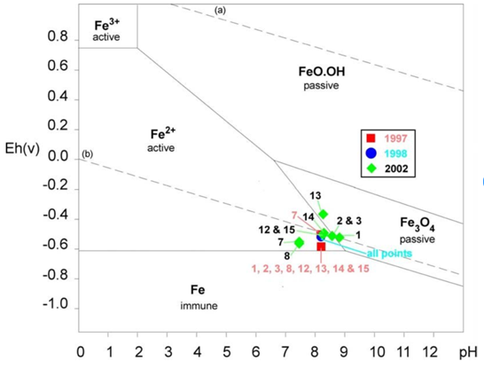
Figure 1. A Pourbaix diagram showing areas where an electrochemical reaction is more dominant. Below -0.7 V, iron is in a zone of immunity, where no corrosion is taking place. ¹
Insurance policies often contain corrosion exclusions, and it can be challenging to understand how liability is apportioned. The damage caused by corrosion is often not directly insured, unless it can be proven that it is linked to a single event and not because of lack of maintenance and/or general wear and tear. On the other hand, the potential damage caused by a corrosion event to nearby components is commonly insured.
A forensic investigator with the right expertise can help in establishing liability. By performing inspections and analysing data, such as ICCP data and ultrasonic thickness testing, they can support in determining how and when degradation started. This can help the ship owner and insurer understand where the liability lies and ensure that the claim is handled quickly and effectively.
Hull Corrosion: A Case Study
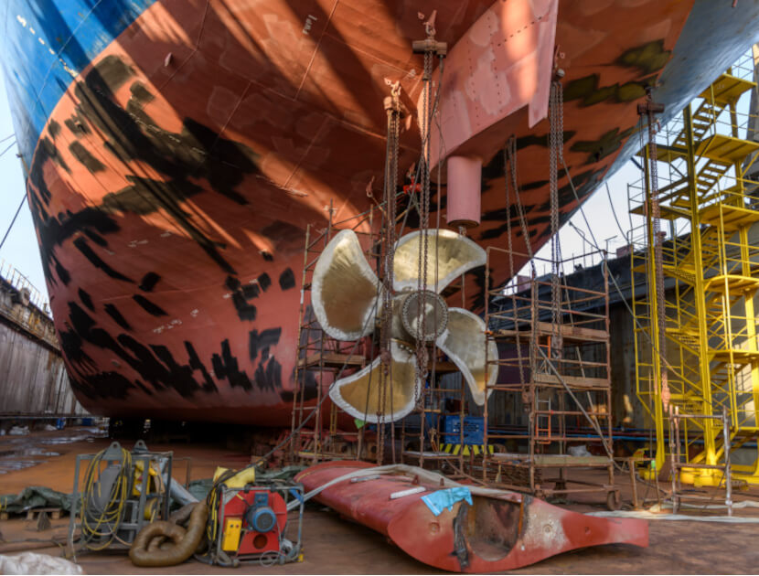
In 2023, during dry docking of an 18-year-old vessel, corrosion damage was observed on the hull, rudder, and propeller blades of the vessel.
Hawkins was instructed to assess what degradation mechanisms had occurred and the nature and timeline of the corrosion, to determine to what extent the widespread corrosion might be related to an alleged prior grounding in South America approximately three years earlier.
I inspected the vessel in dry-dock where I assessed the extent of the damage via ultrasonic testing (UT), confirming that the hull had lost in excess of 20% of its initial thickness. Inspection of the rudder, the propeller blades, and the propeller hubs showed different types of damage. This included impact damage on the propeller, crevice corrosion on the propeller hub (a localised corrosion mechanism), and stray current corrosion damage on the rudder (a mechanism associated with inadequate earthing).
I analysed all available ICCP data and periodic UT measurements. All dry dock UT inspections carried out before this incident indicated that the hull needed minimum re-work.
The measurements conducted in June 2023 show widespread metal loss across all the hull surfaces exceeding 20%; and several spots distributed in separate areas of the hull peaked above 40% metal loss.
During my site visit, I learned that the crew noticed difficulty with operating the ICCP and had ordered a replacement controller, in December 2021. The installation took place seven months later.
The ICCP data review presented an accurate representation of how the vessel corrosion protection system was operated during the previous six years, as shown in Figure 2.
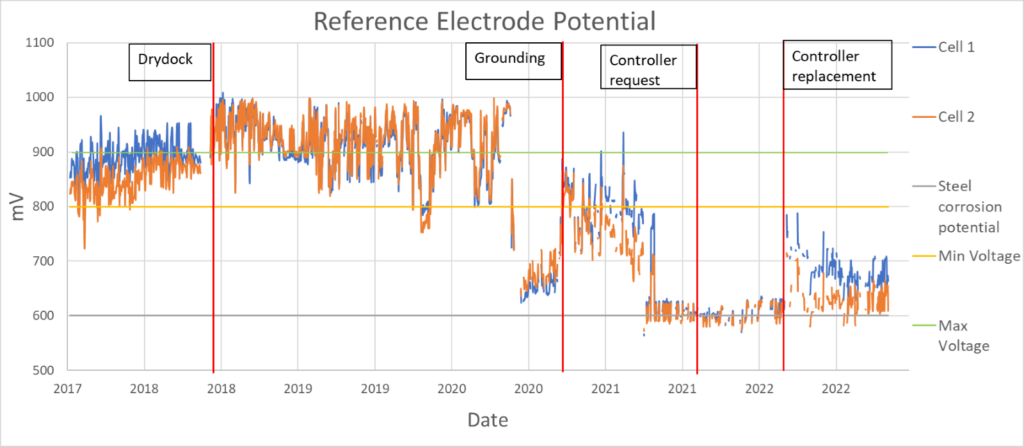
Figure 2. ICCP data review from June 2018 to June 2023.
The ICCP has two reference electrodes, shown in Figure 2 in orange and blue. According to the manufacturer recommendations and as suggested by the Pourbaix diagram in Figure 1, the ICCP should be operated between 800 mV and 900 mV. Operating at a voltage equivalent to a potential below 600 mV results in a completely unprotected hull. But does the system have to remain in this recommended range, or is a higher potential a better approach?
Unfortunately, more is not always better; the high current needed to achieve a potential higher than 900 mV would result in the spallation of the protective layers of paint. If the ICCP is switched off, as when the vessel berths, or if the ICCP malfunctions, bare metal is then exposed to a very corrosive environment, resulting in an accelerated metal loss.
The ICCP data shown in Figure 2 shows the measurements to be erratic over the period reviewed. More specifically, the ICCP, especially past the dry-docking inspection of 2018, has not consistently operated within the recommended guidelines. The measurements appear both above the maximum recommended threshold value, and below the minimum recommended threshold value.
Since 2018, the system had been in the correct window of protective voltage for less than one third of the time i.e. 30.35%, as summarised in Table 1. The percentage of the readings that were found within the manufacturers’ recommended settings are highlighted in yellow.
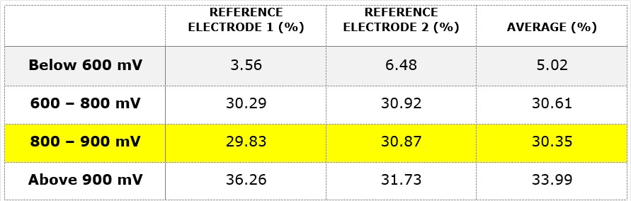
Table 1. Reference electrode readings were obtained from the ICCP measurement output.
The high and low ICCP measurements indicate that the ICCP operation caused the degradation of paint and subsequent degradation of the hull. A review of the ICCP system showed that this was most likely due to a loose electrical connection that would not allow the system to settle on a target value or a malfunctioning reference electrode.
The crevice corrosion in the propeller hub is likely to have been caused by the grounding, which would have created a gap between the gasket, the hub, and the propeller, facilitating water ingress, and leading to corrosion. Damage to the propeller hub was not initiated by the ICCP malfunction, but it is probable that the lack of appropriate ICCP protection exacerbated the issue. A hull protected by an adequately working ICCP and by paint, should undergo minimal material loss. Using Faraday’s law, I was able to calculate the expected metal loss, showing that the hull would have sustained the majority of its metal loss between September 2020 and June 2023.
I calculated that the hull would have experienced the following lower and upper bound corrosion rates:
- Lower bound: = 0.58 to 0.63 mm/year
- Upper bound = 1.25-1.3 mm/year
The upper bound values suggest that a certain portion of the hull might have exceeded 20% metal loss as early as December 2022.
To confirm whether there might have been other potential causes of corrosion, I performed a bulk characterisation of a retained hull sample. I performed Induced Coupled Plasma – Optical Emission Spectroscopy, which confirmed that the steel was of the right composition and therefore was within specification. To rule out a contamination issue, I had collected oxides samples during my site visit on which I performed an elemental characterisation, employing energy-dispersive x-ray. This showed that all elements found were consistent with the average composition of seawater, ruling out the possibility of contamination.
Conclusions
The forensic investigation I performed enabled me to conclusively assess the cause of the corrosion damage, ICCP malfunction, and rule out secondary causes, such as suboptimal metal composition, chemical contamination, or the grounding that occurred three years prior.
I was also able to establish an accurate timeline of corrosion degradation and how rapidly the metal loss had taken place. Given this, the insurer was able to use the information gathered to expedite the claim.
About the Author
Dr Giuseppe Scatigno is a corrosion and materials engineering expert with Hawkins & Associates. He specialises in corrosion, materials, mechanical and engineering failures. He has provided expertise on cases worldwide regarding materials science & metallurgy, failure modes in metals, and structural integrity. His experience spans industries including nuclear, oil & gas, and renewables and he has published over 20 conference and journal papers on his academic research, contributing to establishing the corrosion management of new-build nuclear plants in the UK.
¹[Macleod, Ian & Morrison, P & Richards, Vicki & West, N. (2004). Corrosion monitoring and the environmental impact of decommissioned naval vessels as artificial reefs. 70. 592-297]