GEOTECHNICAL ENGINEERING
Geotechnical engineering is a sub-branch of civil engineering, focusing on the behaviour of rocks and soils, often in relation to soil-structure interaction. Geotechnical engineers design and construct earthworks, foundations, slopes, retaining walls and other underground structures. The soil-structure interaction aspect requires detailed knowledge and experience of soil and rock mechanics along with engineering geology and structural engineering.
Civil engineering and building failures are often caused by geotechnical issues and these can be grouped by errors / omissions at the different stages of the project: ground investigation, design, and construction.
GROUND INVESTIGATION
Soils are not like man-made materials such as steel and concrete in that they are three-phase, consisting of solid soil particles, water and air voids. Consequently, soils exhibit a wide range of physical and chemical properties, even within the same site location.
It is crucial to investigate the suitability of ground conditions prior to the design of any construction project. This will enable the necessary information to be gathered about the ground below the site to allow an economic and effective design to take place. Clients are often unconvinced of the worth of a good ground investigation (GI) and often want to spend as little as possible on it or not do it all. This is a false economy, as often the GI will allow a cheaper design and construction phase, or identify a hazard that would have cost many times the price of the GI to put right after construction.
A well planned GI begins with a desk study, which involves researching historic maps and existing geological information to give an indication of what soils are likely to be found and what historic industrial activity has occurred on site. Concise, tabulated geo-hazard information can be purchased at this stage to give an indication of expected levels of pollution, likelihood of flooding, presence of voids and other hazardous characteristics that can then be investigated further.
CASE STUDY 1: A SINKHOLE ON SCHOOLS GROUNDS
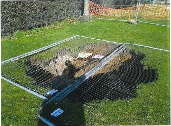
The importance of a good desk study is exemplified by this case where a sinkhole opened up in the grounds of a school (Figure 1). The sinkhole was initially estimated at approximately 2.5m wide and 10m deep, equating to a volume of approximately 50m3.
No desk study had been carried out and the GI report concluded that the likelihood of voids on the site were low. This was despite having identified the presence of chalk strata on the site which is renowned for dissolution features that can develop into sinkholes.
I carried out a post-failure desk study and found online historic maps that showed that the area had been used as a chalk quarry in the 1800s. These quarries were often backfilled poorly leaving a potential void below ground. The thinned out chalk in these areas is also susceptible to dissolution, where heavy rain, slightly acidic due to C02 absorption, dissolves the chalk. A void forms in the chalk, or pre-existing voids grow, and when the surface becomes unstable it collapses into the void forming the sinkhole. The term often used for a sinkhole that forms due to man-made activity such as mining or quarrying is a ‘crown hole’.
In this case, if a thorough desk study had been carried out prior to construction, the potential for this geo-hazard to develop would have been highlighted and mitigation measures could have been carried out to prevent catastrophic failure. The sinkhole was made safe by filling with lightweight foamed concrete and turfed over. However, it took almost 350m3 of material to fill the cavity, rather than the initial estimate of 50m3, indicating that the quarrying / mining was quite extensive in the area.
The site investigation (SI) part of the GI should consist of a mixture of shallow trial pits and deep boreholes to investigate every strata of the ground on the site to a depth at least 5 m below the intended depth of the structure, including foundations. The number, spacing and depth of the trial pits and boreholes will depend on the size of the site, the expected ground conditions based on the desk study and the type of structure being constructed.
In-situ testing should be carried out in the boreholes or trial pits such as SPT (standard penetration test), shear vane and CPT (cone penetrometer test) to give an indication of strength. In addition samples should be taken to allow laboratory testing to be carried out, such as Atterberg limits (to provide moisture and plasticity characteristics), shear tests (to provide angle of shearing resistance) and triaxial tests (to provide shear strength and angle of shearing resistance).
It is critical to the success of the project that the SI should also identify the depth of groundwater at the site and ideally how this depth changes with rainfall and seasons. Getting the ground water profile wrong is one of the major causes of failures in ground structures, since higher ground water levels have the effect of both increasing loads and reducing soil strength.
CASE STUDY 2: A SINKHOLE BENEATH A HOUSE
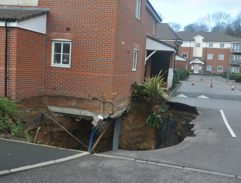
This case shows that even well planned and executed site investigations cannot guarantee that all geo-hazards are identified prior to the construction stage. The case involved a 6m diameter and 6m deep sinkhole that opened up below the corner of a semi-detached house on a recently constructed housing estate after extremely heavy rainfall (Figure 2).
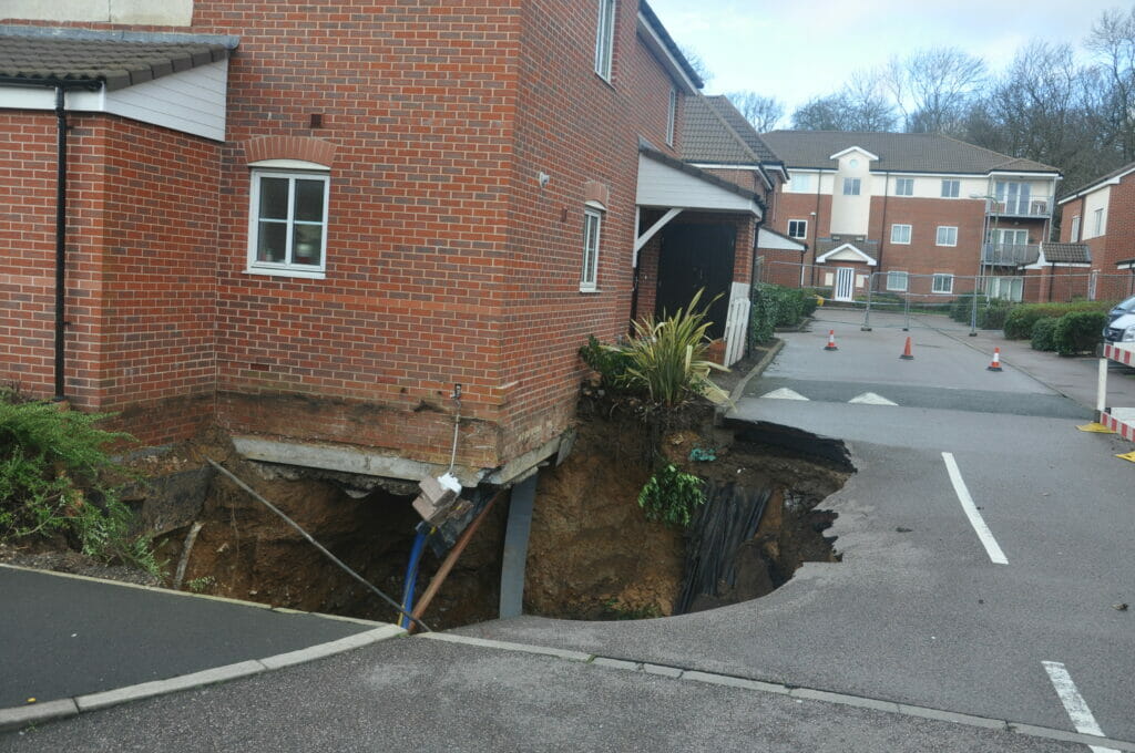
The house had continuous flight auger (CFA) piled foundations with connecting ground beams and so although one pile was swallowed by the sinkhole, the stiffness of the ground beams prevented a catastrophic collapse of the house. Initially the whole estate had to be evacuated before the extent of the sinkhole was established by boreholes and the sinkhole filled with 200m3 of lightweight concrete.
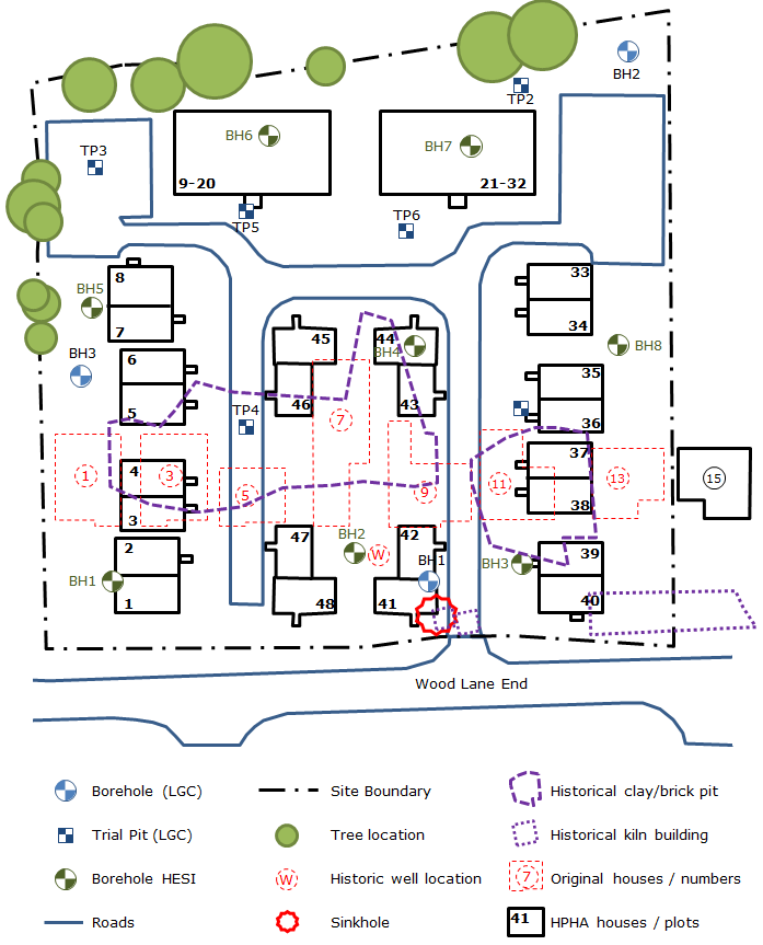
I reviewed the GI reports and found that a full and thorough desk study as well as two SIs had been carried out. The desk study involved research into historical maps, historic boreholes and the purchase of full geo-hazards information. My own desk study found historic maps that showed the site was a former clay brick pit with associated kilns (see Figure 3) and this was reflected in the desk study carried out for the project.
The first SI consisted of a general investigation that recommended further deeper boreholes to be sunk in light of the high potential for dissolution features and the presence of historic mining activity in chalk on this site, which had been identified by the desk study.
The second SI consisted of boreholes drilled to 20m depth at a spacing of no more than 45m, with associated SPT and laboratory testing carried out. After reviewing the rainfall data relevant to the incident, as well as the geology and historic maps, I concluded that the sinkhole was caused by a sub-surface chalk dissolution feature or mine-working being enlarged by the heavy rain just prior to the failure. These thorough investigations were still not sufficient to identify this localised sub-surface void.
However, after reviewing the piling method statement I found that the pile installation had not been carried out to the latest industry standards with respect to piling in chalk, where probing ahead of the pile is recommended. This is good practice in areas of known dissolution features and consists of probing with a small diameter borehole or cone penetration test (CPT) at each pile location to a depth at least ~5m deeper than the pile depth to make sure the ground under the pile is intact and does not contain a dissolution feature. If this had been carried out there is a possibility that the sub-surface void that developed into the sinkhole could have been identified and filled prior to failure.
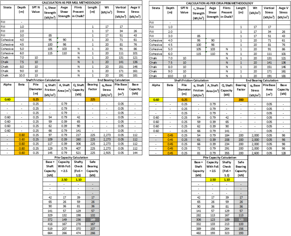
In addition, after reviewing the pile design calculations, I found that the pile design did not comply with the latest design guidance for chalk and so was under-designed. The issue was with the high values of the empirical skin friction factor ‘β’ and the base capacity empirical factor that had been used.
The factor ‘β’ converts the vertical effective stress in the soil to a ‘moderately conservative’ skin friction value and is usually taken as 0.8 for CFA piles. However, in weak chalk, especially with flints, both of which were present in this case, the guidance recommends that this factor should be reduced to 0.45.
The base factor converts SPT results (‘N’ values, which is a count of the blows required to drive a standard size bit with a standard weight hammer into the ground by 300mm) into a reasonable base capacity and it is recommended that a factor of 200 is used in chalk strata, rather than the 225 that was used in this case. As a result the piles were under-designed by approximately 20% with a safe bearing capacity of 123kN versus the original design of 146kN (see Figure 4).
In both of the above examples poor site investigation led to ground failures and damage to property.
ABOUT THE AUTHOR
Andrew Reeves is a Chartered Civil Engineer with a background in the design and construction of large-scale geotechnical solutions in UK, Germany and Hong Kong, including deep basements, large diameter bored pile foundations, retaining walls and tunnels.
More recently Andrew has carried out structural design in timber, masonry, steel and reinforced concrete as well as fire risk assessments for domestic and small-scale buildings in the UK.
Since joining Hawkins in October 2013, Andrew has investigated hundreds of building-related failures including the collapse of structures, flooding of buildings and land, failure of basement waterproofing, failure of retaining walls and serviceability issues caused by subsidence.
