Safety considerations in fairground rides: Hawkins investigators are often asked to consider the forces generated by machinery and how those forces translate into injuries sustained by the people carried in, on or nearby those devices. A common example of this is fairground/theme park rides. Such rides often involve high levels of g-force and require a detailed understanding of the tolerance of the human body to high levels of acceleration.
Since travelling fairs first began to appear, the appetite of the general public for thrill seeking amongst loud music, flashing lights and sugary snacks has only grown apace. Over the years, fairground rides gradually evolved from horsepower to steam and then, in the wake of World War I, electrically powered motors, which ushered in ever greater speed and acceleration. However, as the level of thrills has increased, so has the potential for injury.
Modern fairground and theme park rides can be extremely complex pieces of machinery, incorporating brute force heavy engineering side by side with sophisticated electronic control systems, which keep passengers and machinery separated. As such, their safe operation is extensively regulated[1][2][3].
In the aftermath of an incident, manufacturers, operators and passengers are typically looking to establish whether or not fairground equipment has been designed and operated in a safe manner. In the UK, those safe practices are covered by national design standards that define, amongst other things, the “envelope” within which a ride is permitted to operate (e.g. separation, speed, g-forces).One such case where g-forces became an issue was an injury sustained on a classic travelling fair ride known as the ‘Twister’. The ride required riders to sit in a set of three carriages that rotated whilst simultaneously being spun at the end of a longer arm. Some of the incident passengers had claimed chest and neck injuries from excessive g-forces that caused them to pile up against the side of the carriage.

The design safety standard BS EN 13814 details the physics of a few of the more common rides of which the Twister is one. Although ‘common’, the physics describing the g-forces on a rider at any given time in any given direction is not straightforward.
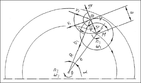
The rider travels through a looping path and is pulled in all directions with the peak g‑forces occurring when the rider is on the outside of the circle of the larger rotating arms. The force experienced is a combination of two sets of centripetal force from the counter rotating arms (the force you feel pushing back towards the inside of a bend as you travel through it) and a Coreolis force as the rider moves towards and away from the central spindle of the ride.
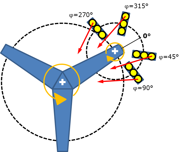
The bench seating fitted in the carriages was orientated such that this peak of g-forces occurred towards the left of the riders. Therefore, to avoid crushing, the operator had insisted on the heaviest rider sitting to the far left so that they would rest directly against the side restraint of the carriage and not bear down on the other riders.

The initial modelling, and later direct measurements using an accelerometer, showed that g-forces up to 2.6 g were possible at the maximum speed. In the absence of effective restraint, two of the riders bore down on the third, outermost, rider with 2.6 times their combined weight resulting in a load of almost 590 kg (92.8 stones) between the left hand side of the third rider’s body and the side of the carriage. Therefore, even though the heaviest rider was on the left, the forces were still sufficient to cause injury. Furthermore, given the changing direction of the g-forces as the ride rotated, the biomechanical g-force limits set within BS EN 13814 to prevent neck injuries had also been exceeded.
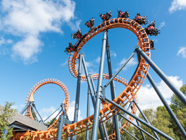
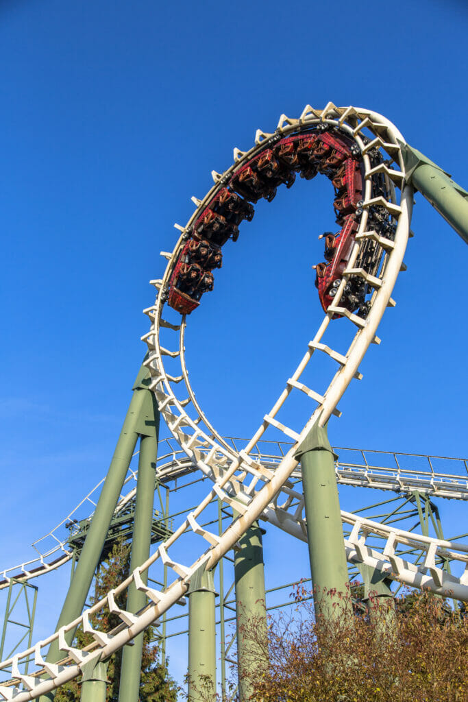
High g-forces are commonly encountered in the design of rollercoasters. Vertical loops, in particular, are problematic primarily because of the limits of typical human performance. Depending upon an individual’s ‘g-tolerance’, the oxygen supply to the head can be interrupted at around 5g to 6g, resulting in unconsciousness if sustained over time. If circular loops are used then, in order to ensure that the train doesn’t fall off the track at the top of the loop, the speed at which the train would have to enter the loop would result in excessive g-forces at the entrance and exit of the loop.
For this reason, roller coaster loops are often designed in the shape of a clothoid loop where the radius of curvature at the entrance and exit to the loop is much greater than at the peak. Using this clever bit of geometry, the speed of the train at the entrance and exit of the loop can be reduced so that the g-forces don’t get so excessive as to make the riders pass out, yet the train doesn’t fall off at the top of the loop.
The national safety design standards also detail the controls that must be in place to allow both safe operation of a ride, as well as the ability of the ride to be made safe should an incident occur. A near fatal incident involving operator controls occurred on the Magnum Force roller coaster at Flamingo Land, Yorkshire in June 2004.The operator in that case had taken a short cut through the inner compound of the ride when they were struck by the train as they were squeezing between fencing and the track itself. The ride was originally manufactured by Schwarzkopf in 1984 and was the world’s first roller coaster with three vertical loops, however, by the time of the incident, the roller coaster was already 20 years old and the adequacy of the controls came under intense scrutiny.
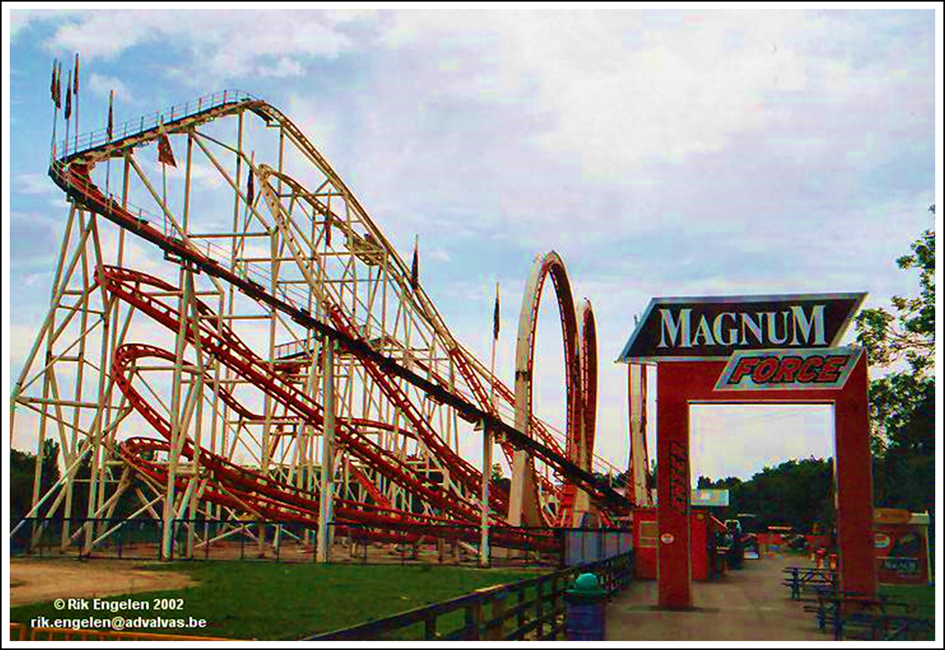
The collision was initially investigated in 2004 by the Health and Safety Executive (HSE), who questioned the adequacy of the barrier that the operator had crossed (it was a looped section of chain).However, the focus subsequently shifted to the actions of the second operator who had called out to his colleague rather than immediately hitting the emergency stop button that was fitted. The new imperative was to consider whether or not, if the emergency button had been pressed straight away, the collision would have been avoided.
Roller coaster trains are generally, by definition, ‘coasting’ around a track, i.e. they are not under power and do not carry their own motors. The trains are accelerated and braked by equipment that is mounted at specific points along the track. This results in a track being divided into a number of sections, each terminated by a set of braking equipment. By this method, multiple trains can be operated simultaneously on the same track. Both in the event that one should begin to gain on another, and if an emergency stop button is pressed, the trains can be braked at the end of the separate sections that they occupy. However, even after a signal has been sent to the braking equipment, it follows that a train will continue to coast under the influence of gravity until it reaches the end of the section of track where those brakes are fitted.
In the case of the Magnum Force, there were six sections and during my investigation, I needed to establish the timing of the trains on the track immediately before the incident, in order to assess the effectiveness of pressing the emergency stop button. In other words: was the train already beyond the braking equipment, such that operating the emergency stop button first would have made no difference to the outcome?
Unfortunately, by the time of my investigation in 2006, the Magnum Force had already been sold, dismantled and installed in a theme park in Mexico City. So, barring a trip to Mexico, all that was available to calculate the timing of the rollercoaster was the original technical drawings produced by Schwarzkopf.
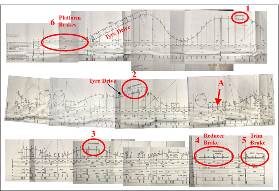
Using what was known about the settings of the motor and brake sections, I modelled both the acceleration of the trains under the influence of gravity, as well as their movements through the six track sections and the various clothoid loops, drops and banking. The physics established that the train had almost certainly already passed the last brake section when the operator was spotted: i.e. operating the emergency brake would not have prevented the incident in this case. This determined that the actions of the operator had not contributed to the collision.
Thankfully, major fairground accidents are relatively uncommon, and there is no doubt that rides and roller coasters will continue to be one of our favourite thrills. Nonetheless, if the fun ends unexpectedly, Hawkins is able to provide in-depth analysis of the operation and management of fairground equipment.
ABOUT THE AUTHOR
Dr John Camplin is a Chemical Physicist who also holds a doctorate in Surface Chemistry. Prior to joining Hawkins in 2004, he worked for 12 years in materials science in both the UK and USA and now investigates engineering and materials failures in addition to the reconstruction of road traffic incidents. John has a special interest in fairground equipment, head protection and the biomechanics of the human body.
