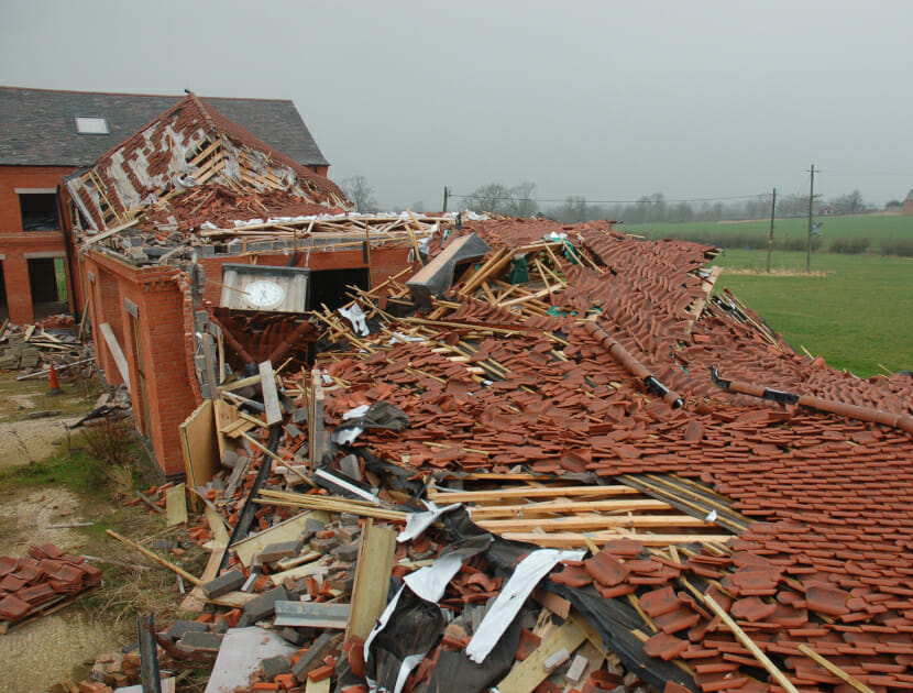
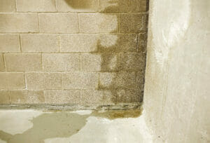
Whether it be wind, snow or rain, the weather can have a significant impact on buildings and infrastructure, causing structural damage or flooding. While damage from snow is typically restricted to roof collapses, wind has the potential to cause a wide range of failures, including wall collapses and the detachment of cladding and roof coverings.
In the UK, the wind speed that buildings are subjected to is rarely in excess of that which they should have been built to withstand. When failures do occur during high winds, the underlying cause is often defects in the design or construction of the building, which means there is frequently the potential for a claim against a third party, such as the designer or installer. When investigating such failures, one of the questions that Hawkins’ Civil Engineers need to answer is: “What wind speed should the building have been designed for?”
To answer this question, it is necessary to carry out an assessment using the design principles laid out in the relevant British Standard, BS EN 1991-1-4:2005 Eurocode 1: Actions on Structures- Part 1-4: General Actions – Wind actions. Designing for wind loading can be complex, and this article provides an overview of some of the key factors that must be considered. This is followed by a description of the Beaufort Scale, as well as some case examples.
DESIGNING FOR WIND LOADING
The requirements of the Building Regulations, in relation to wind loads, simply say that: “the building shall be constructed so that the combined dead, imposed and wind loads are sustained and transmitted by it to the ground safely,” and that in assessing whether this is achieved, “regard shall be had to the imposed and wind loads to which it is likely to be subjected in the ordinary course of its use for the purpose for which it was intended.”
Guidance on how to meet these requirements is contained in Approved Document A – Structure (ADA), which in turn refers to the relevant British Standard mentioned above, BS EN 1991. ADA also includes simplified guidance that can be applied to certain residential buildings, and other small buildings of traditional construction. However, for larger buildings BS EN 1991 must be used.
The design procedure begins with the use of a map to select a wind speed based on geographical location, referred to as the ‘fundamental basic wind velocity’. This represents the mean wind velocity at 10m above sea level, measured over a 10 minute period, that has a 1 in 50 year return period. The value of the wind velocity varies across the UK and has higher values in the north; in England and Wales it is typically between 21 m/s (47 mph) and 24 m/s (54 mph). Having selected the appropriate velocity, it is then modified with factors to take account of specific features of the building, as well as its location and surroundings, including: the altitude of the building site, the height of the building, the type of terrain, the orography of the landscape, the presence of other buildings and the distance from the sea. The way in which these factors are applied is dependent on the building height and the shape of the landscape.
The orography factor accounts for the increase of mean wind speed over isolated hills and escarpments. To determine its value, it is necessary to consider the height and length of the slope of the hill or escarpment, and the position of the building relative to the crest.
The modified wind velocity is converted to a pressure, which is proportional to the square of the velocity. This gives the ‘basic velocity pressure’ that is then multiplied by the exposure factor to give the ‘peak velocity pressure’. The exposure factor is based on building height and the distance from the upwind shoreline and accounts for mean and short-term velocity fluctuations (i.e. gusts). For example, a 10 m high building that is 10 km from the coast would have an exposure factor of 2.5, so the peak pressure would be 2.5 times the basic pressure. This would be equivalent to multiplying the basic wind speed by 1.58 (i.e. the square root of 2.5), typically taking it up to around 80 mph. For taller buildings closer to the sea, the exposure factor could be around 3.5, giving an equivalent wind speed in excess of 100 mph.

For high buildings in locations where the orography is considered significant, a turbulence intensity factor must be determined together with a turbulence correction factor for buildings in urban areas.
After applying the appropriate factors, the peak velocity pressure is converted to a wind pressure on a surface of the building by multiplying it by an appropriate pressure coefficient. The pressure coefficients, which can be positive or negative, vary considerably depending on which part of the building is being considered. Negative coefficients reflect the suction effect of the wind that tends to occur on surfaces that are not facing towards the wind.
Both the external wind pressures and the internal wind pressures (which exist due to either openings in the building or porosity of the building fabric) are used together with size factors and dynamic factors to calculate the wind forces that must be accounted for in the overall structural design of the building and the design of the individual building components and fixings. The size factor is influenced by both the height and breadth of the building, and it accounts for the reduction effect on the wind action due to non-simultaneous action of gusts over external surfaces. The dynamic factor accounts for the effect of fluctuating wind loads in combination with the resonance of the structure.
THE BEAUFORT WIND FORCE SCALE
Table 1 below shows part of the Beaufort Scale with descriptive conditions based on the effects of the wind on land rather than at sea. The values shown are mean speeds, usually over 10 minutes by convention, and not gusts. The speeds relate to that measured 10m above ground level. This shows that the fundamental basic wind velocity used as the starting point in design is typically within the range of a Force 9 strong gale and that with the altitude factor applied, that velocity could fall within the range of a Force 10 storm. With other factors applied, the design wind velocity would be considerably higher. However, since the value includes gusts, it cannot be directly compared with Table 1.

EXAMPLES OF WIND INDUCED FAILURE INVESTIGATIONS
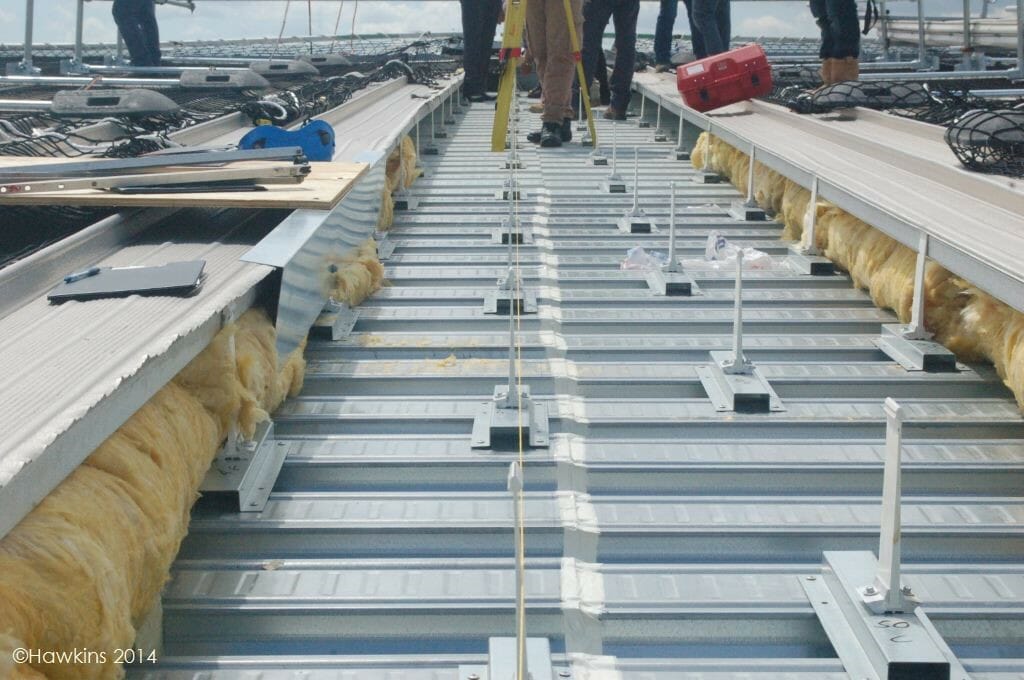
Following a period of particularly high winds across the UK, Hawkins received three separate instructions to investigate the cause of damage that had occurred. The cases included the loss of a large area of sheet metal roofing from a grandstand roof, the loss of large glass panels from a canopy of another grandstand at a different site and the detachment of cladding panels from a college building.
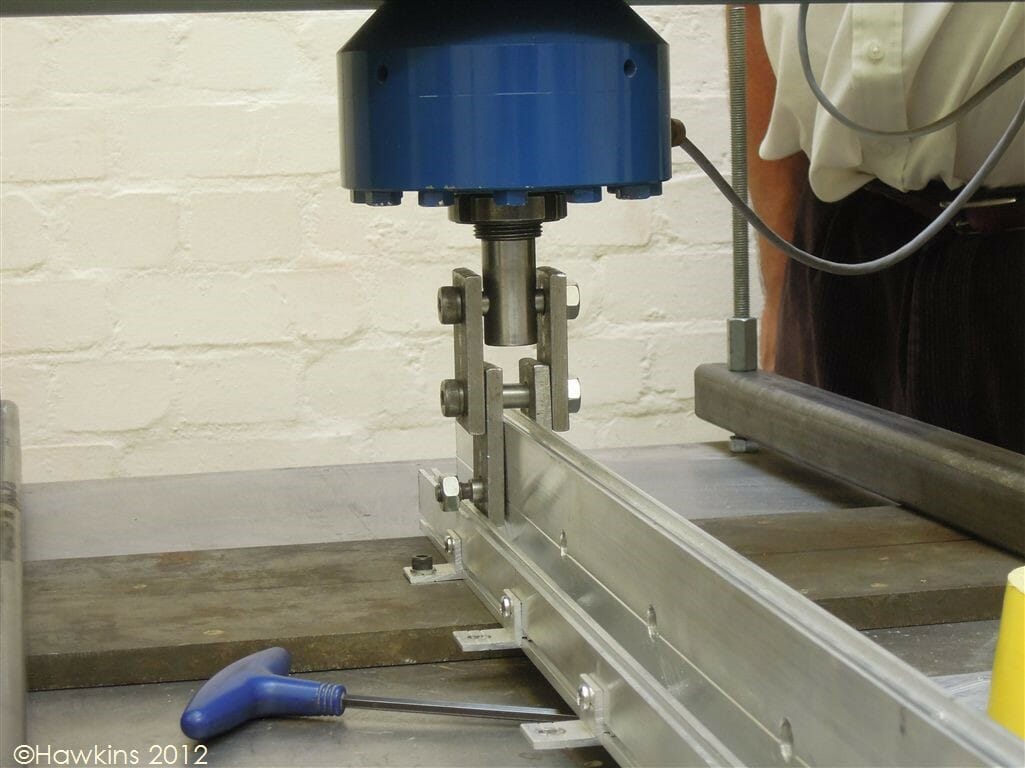
One of the grandstands was in an exposed elevated position. Hawkins carried out a detailed examination of the roof and a review of the design of the building in relation to wind loading. This lead to further work involving load testing in the laboratory of brackets used to secure the roof covering. The objective was to establish whether the brackets were capable of resisting the likely wind load.
Witness accounts indicated that the wind had been particularly strong at the site of the failed glass canopy. Hawkins carried out an inspection of the panel fixings and commissioned a forensic meteorologist who determined that the likely maximum gust speeds at the time of the incident were 65 mph and therefore not extreme. Load testing was carried out to establish the variation in performance under wind loading with alternative fixing arrangements. The objective of the investigation was to discover whether the failure was caused by extreme winds or by issues relating to the design or installation of the canopy.
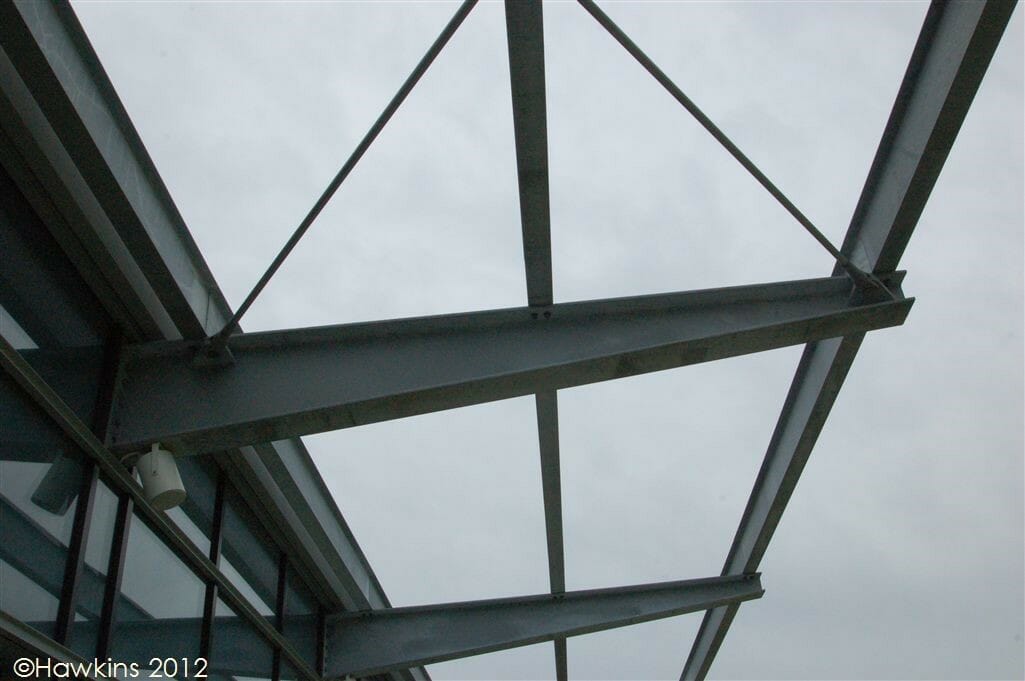
In the case of the failed cladding, our investigation revealed that the failure occurred because an error in the design had resulted in excessive spacing of the rails that supported the cladding.
Hawkins have investigated numerous cases involving failure of membranes on flat roofs of large commercial buildings during windy conditions, with mean wind speeds ranging from 30 to 50 mph. These include incidents where the whole roof covering had blown from the building, resulting in further damage caused by the ingress of rainwater. One such incident occurred during the St Jude’s Day Storm. Multiple building elements failed, and it was necessary for Hawkins to advise on the likely influence of the identified defects in the context of the damage that occurred. This required careful consideration of the way in which the wind acted on the building and an analysis of the sequence of the failure.
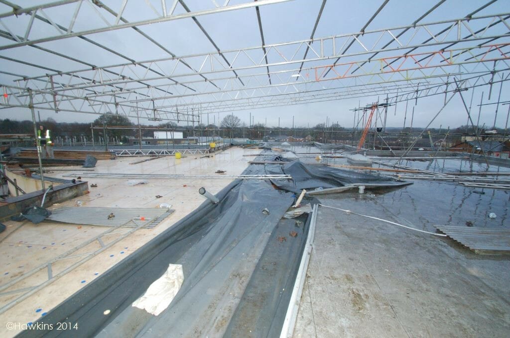
Roof membranes are typically fitted to underlying insulation and can either be adhered or mechanically fixed with specialist screws. Typically, the cause of the failure has been related to either poor workmanship (e.g. lack of adhesive and/or incorrect spacing of fixings) or the use of insulation that was not suitable for use with an adhered membrane.
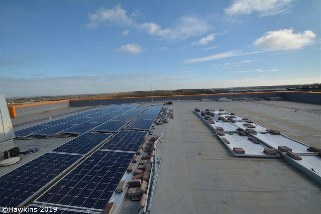
Following the St Jude’s Day Storm, the UK Met Office decided to implement a storm naming system. Storm Doris resulted in the collapse of a ceiling causing personal injury. Investigation showed that the ceiling had been poorly supported and also subjected to deterioration from water ingress; the storm was not to blame. Storm Gareth caused a large number of solar panels to fly from the rooftop of a commercial building. Again, the storm was not to blame; the incident occurred due to a lack of ballast.
While most cases involve damage to roofs, defective design or construction can lead to the collapse of the whole building. A newly constructed two storey building of conventional brick construction with a pitched tile-covered roof completely collapsed during a Force 9 strong gale. Hawkins’ investigation revealed that the building had numerous deficiencies with the most significant ones being its lack of lateral restraint, as well as its excessively slender walls. The building had been constructed without sufficient input from a structural engineer.
A rare example of severe building damage potentially being a result of extreme winds, rather than an underlying defect, occurred during Storm Katie. Investigations by others had blamed characteristics of the building for the failure of a wall, but calculations by Hawkins showed that the calculated wind pressure used in the design could have been exceeded. Weather records showed that a gust of over 100 mph had been recorded only 3 miles from the incident location on the south coast of England.
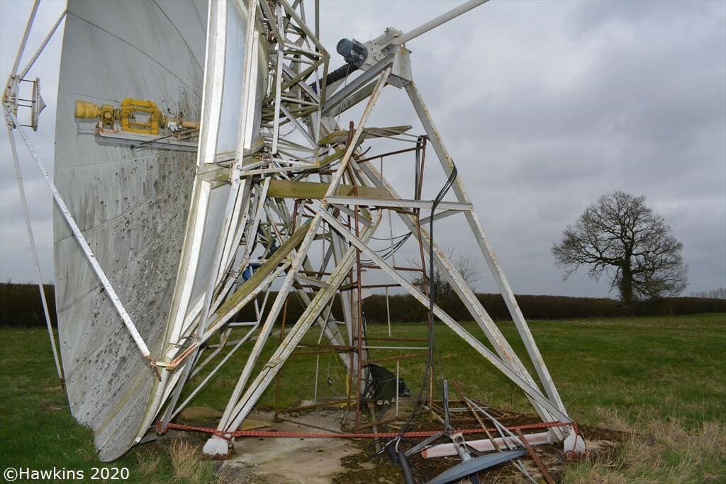
During Storm Ciara, a structure supporting a communications antenna partially collapsed. Forensic examination of bolted connections revealed that several connections had probably failed prior to the storm.
Hawkins also investigate personal injury cases relating to the failure of walls and hoardings. In a case involving the collapse of a site hoarding onto a pedestrian, the assessment showed that there were defects in both the design and installation of the foundations supporting the hoarding. The wind load at the time of the collapse was probably only one quarter of that which the structure should have been capable of withstanding. Calculations were carried out to determine whether the hoarding would have collapsed if the foundations had been installed in accordance with the design.
ABOUT THE AUTHOR
Ian Major is a Chartered Civil Engineer who had a 15 year career in the design and construction of infrastructure projects prior to joining Hawkins in 2010 to begin a career in Forensic Engineering. In addition to investigating incidents involving building defects, structural failures, flooding and water ingress, Ian determines the cause of fires and fire spread.
