20 7481 4897")


Steam Turbines operate for extended campaign periods ranging from 3 to 9 years with little invasive inspection. Minor inspections of auxiliary components such as valves and gearboxes do occur but most of the daily, monthly, and yearly inspections are of external systems looking for visible degradation (i.e. leaks) and monitoring of water/ steam chemistry and oil condition.
The health and condition of the internal steam path parts in the steam turbine train rely on system sensors to monitor degradation and warn of progressive damage. These sensors cover vibration, pressure, and temperature. If the sensor readings are within expected ranges i.e. below alarms or trip limits set by the original equipment manufacturer, the operator can approach a scheduled major outage with the expectation of finding no abnormalities.
However, I have seen and worked on projects where unexpected damage has been found on lifting the top casing, due to the uniform distribution of the damage around the stage, and the damage being on small “chunky” blades. This is particularly the case with smaller blades in the earlier pressure and intermediate pressure stages, which can be more tolerant to crack propagation, especially in low stress areas such as near the blade tip/shroud.
Rotor repair guidelines in API RP 687 permit a certain depth of grinding to remove damage to the leading and trailing edges. The damage found on one such case was severe enough that the permitted blending in API RP 687 could not be completed and replacement parts needed to be sourced and delivered to the site. This had a significant effect on the outage schedule and consequentially on the loss of generation.
Examination of the vibration data revealed no evidence of expected damage.
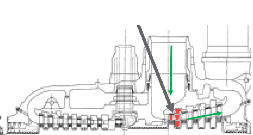
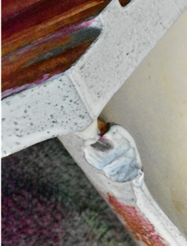
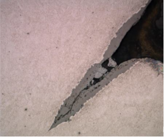
Image 2 shows the location of the stage 1 IP blade and diaphragm and steam flow. The damage was seen on the majority of the stage 1 blades, predominately under the shroud. Typical damage is shown in Image 3.
To cover the likely delays and subsequent generation losses, the operator instigated a claim on their insurance policy. To enable the claim to proceed the insurer requested that the date of the event be determined so that the claim could be assigned to the correct policy year. For insurance purposes, it is important to determine not just the date of detection but the date of occurrence.
From the damage found and the presence of cracking, exposing fresh surfaces to the operating environment reported to be steam pressure of 175 bar and steam temperature of 538°C, it was possible to use the rate of oxidation of martensitic stainless steels (blade material) to determine the approximate time required to form the oxide thickness found on the cracked surfaces.
Applying oxidation theory for a protective oxide scale forming can indicate the approximate time of exposure to the steam environment. The rate of scale growth and therefore thickness is controlled by diffusion of ions through the oxide (parabolic oxidation rate law), and the rate of oxide thickening decreases as the oxide thickness increases such that:

Using Equation 2 (shown above), and widely accepted values for the blade material, the expected oxide thickness over time and at various steam temperatures can be calculated.
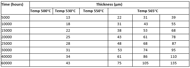
Removing metallurgical sections from various IP blades, mounting the removed sections in a thermos setting resin and preparing to a 1 µm mirror finish enabled the prepared sections to be examined in a polished and etched condition using a metallurgical microscope. Following this, the oxide thickness was measured and the results compared to the calculated thickness obtained using Equation 2.
The areas selected for analysis had all exhibited tearing/cracking, exposing new surfaces to the steam environment thus ensuring that the oxide growth being measured on the freshly exposed surfaces was from the date of impact and not before. In these areas, an estimation of surface exposure time to steam was calculated.
The identified time period was then compared to any planned maintenance or repair work that was undertaken on the steam system to determine any correlation that could explain the ingress of foreign objects into the steam path. Note that at the time of the outage, the upstream steam strainer was not damaged. In this case, the data aligned with work that had been completed upstream of the IP blades on the steam valve several years earlier. It was considered highly likely that during this repair, an item of tooling was left in the steam path downstream of the steam strainer which on startup entered the IP turbine.
Applying oxidation theory in relation to oxide formation on steels in steam service is a well proven method that can enable an estimated time of an impact event to be determined and ensure that an insurer can assign a claim to the correct policy year for financial purposes.
About the Author
Stephen is a forensic metallurgist with extensive global experience in providing independent materials and corrosion advice to multi-national companies in the built and engineering sectors.
He has over 25 years’ experience undertaking failure and root cause analysis for clients in the power, process, and pipeline sectors together with transport and built infrastructure and has acted as an expert witness across the globe.
In the last decade, Stephen has focused on the power sector, helping loss adjusters, insurance companies and owners/operators investigate events in various power plants from renewables (hydro, energy from waste, geothermal (binary and flash units) and wind) to thermal generation assets (coal and gas power plants (simple cycle, cogeneration, and combined cycle)). Investigations completed have covered static and rotating components located within the fence of the power plant. Projects have also included condition assessment of gas and steam turbines, and outage support for operators.